Greenhouses help mitigate adverse weather and enable steady year-round crop production by controlling the microclimate for optimal growth. They are essential worldwide, often yielding significantly better results than open field cultivation, as shown in this 2011 study.
A key advantage of greenhouses is their controlled environment, which makes automating climate control with sensors and actuators highly desirable. This project uses IoT to build an autonomous monitoring and control system that optimizes growth conditions, supported by a web dashboard.
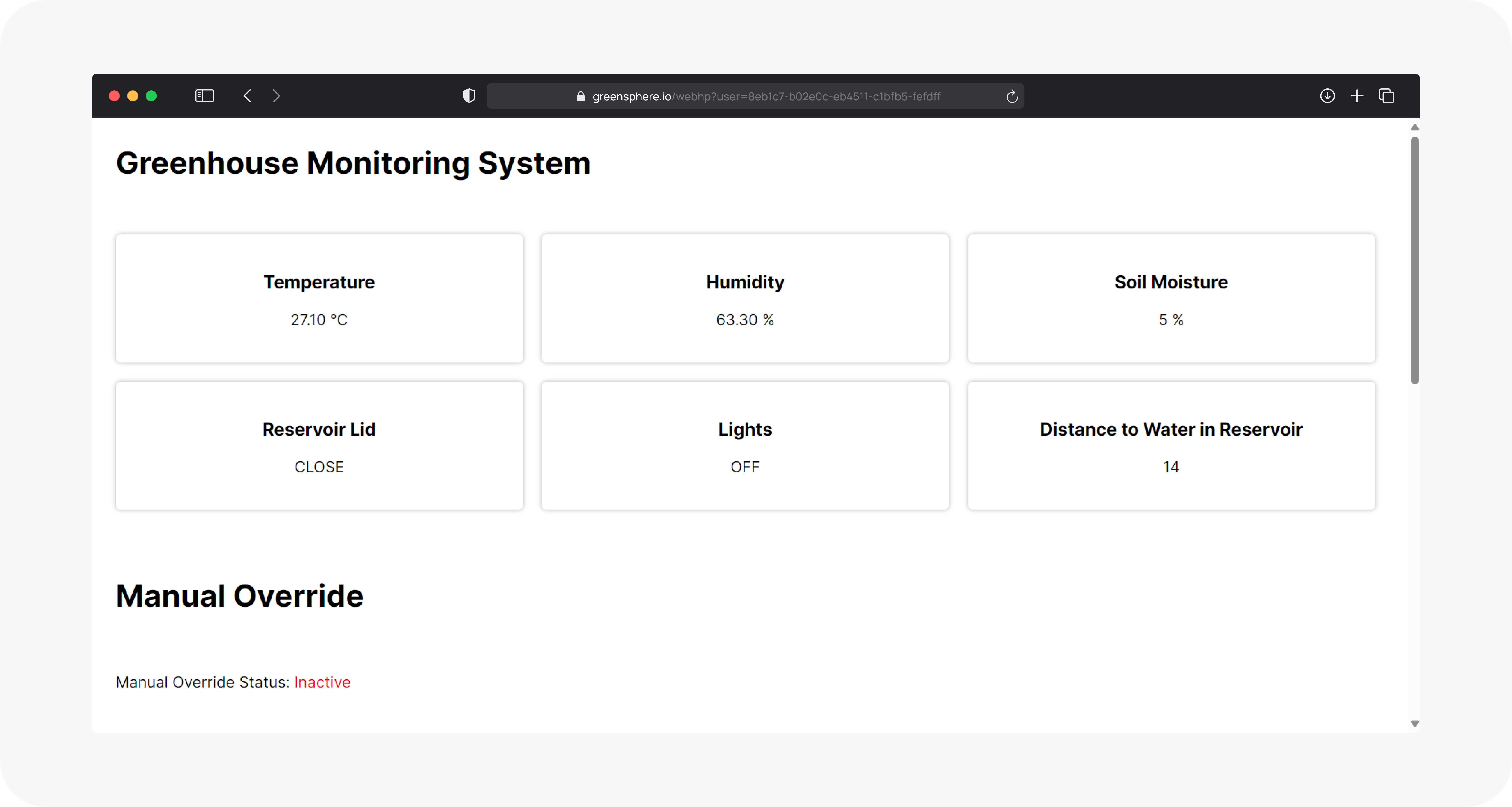
The dashboard offers remote accessibility and a user-friendly interface. It solves the impracticality of checking sensors and manually adjusting each actuator on site by centralizing control—letting you monitor conditions and instantly adjust settings as needed. Manual control is optional; when off, the system manages actuators automatically based on preset thresholds.
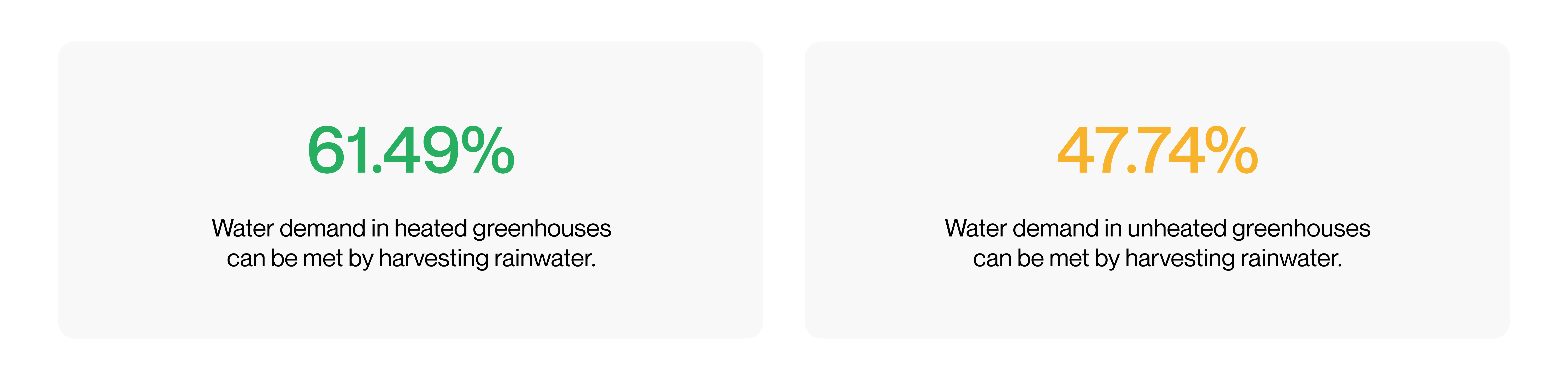
Two key features of this IoT system are its rainwater collection and precise control over temperature and humidity, both critical for boosting water efficiency and crop yield. According to a study published in the International Journal of Research - GRANTHAALAYAH, rainwater harvesting can significantly reduce water demand in greenhouses.
A 2021 study highlights that different plants require different optimal growing conditions. Predefining these on the microcontroller can become a drawback when switching crops between cycles. Allowing users to adjust setpoints makes the system adaptable to various crops, enhancing its long-term value.
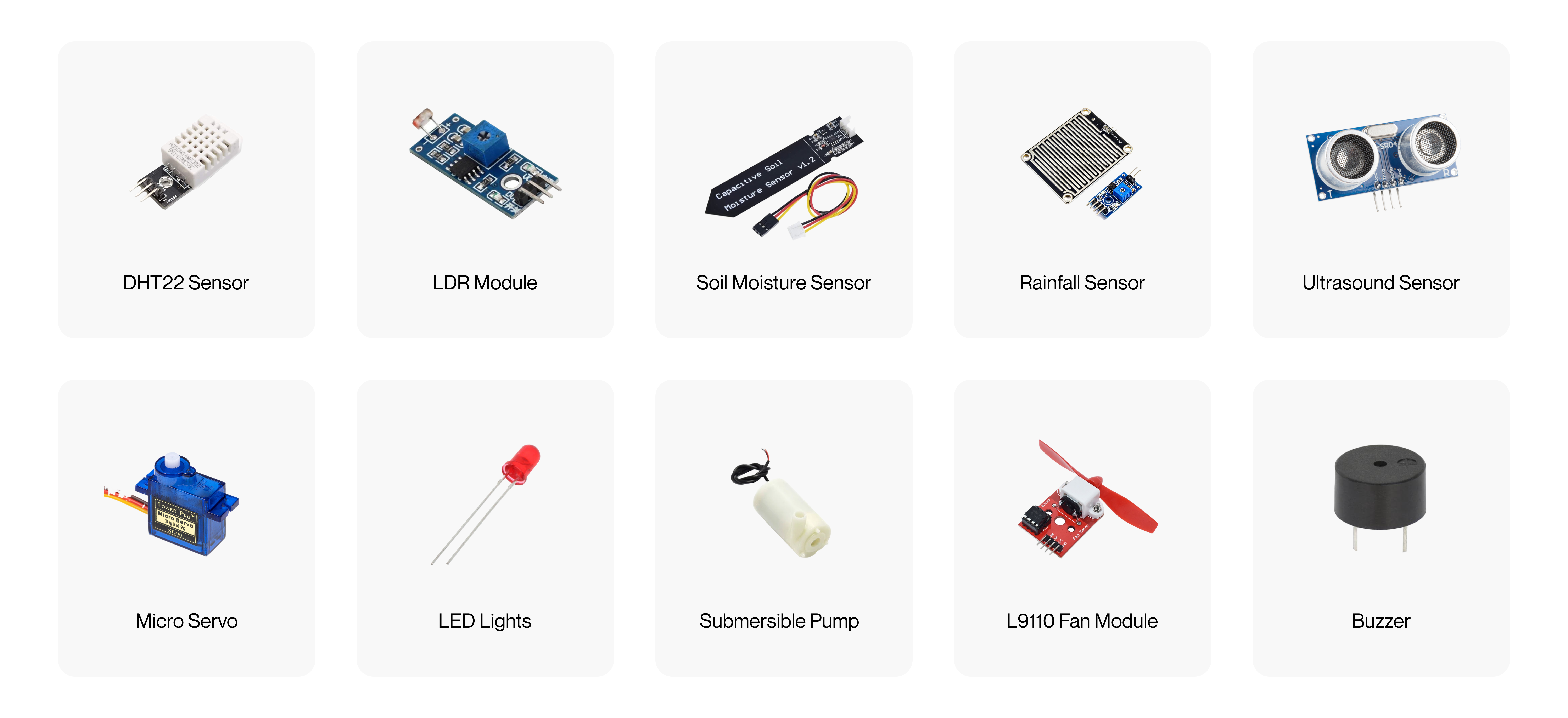
All sensors and actuators used in this project are compatible with the NodeMCU ESP8266 microcontroller. Here’s the full list of components.
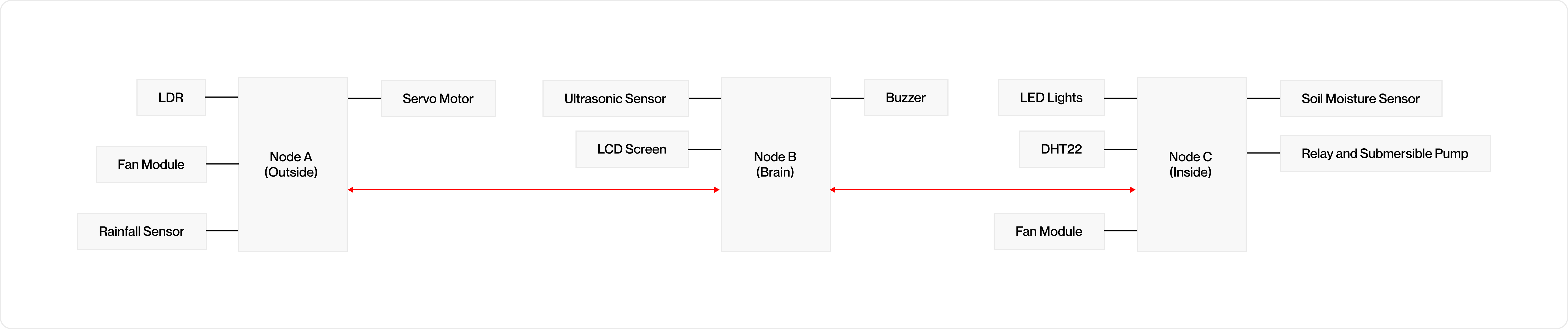
The system divides sensors and actuators across three dedicated nodes—“Brain,” “Inside,” and “Outside.” This distributed architecture avoids overloading a single microcontroller, enables flexible hardware placement, and keeps the codebase modular and clean. It also simplifies troubleshooting and makes future expansions straightforward.
The Brain Node acts as the central controller. It gathers sensor data from both the Inside and Outside nodes, compares readings to optimal values, and sends commands to activate or deactivate actuators as needed. This centralized decision-making ensures the system remains consistent and coordinated.
Located inside the greenhouse, the Inside Node monitors temperature, humidity, and soil moisture using DHT22 and soil sensors. It controls devices like the fan and submersible pump to adjust internal conditions directly.
The Outside Node tracks external factors with the rainfall sensor, LDR, and an ultrasonic sensor, and also manages the micro servo for the rainwater system and an extra fan module.
This diagram illustrates the overall IoT system design.
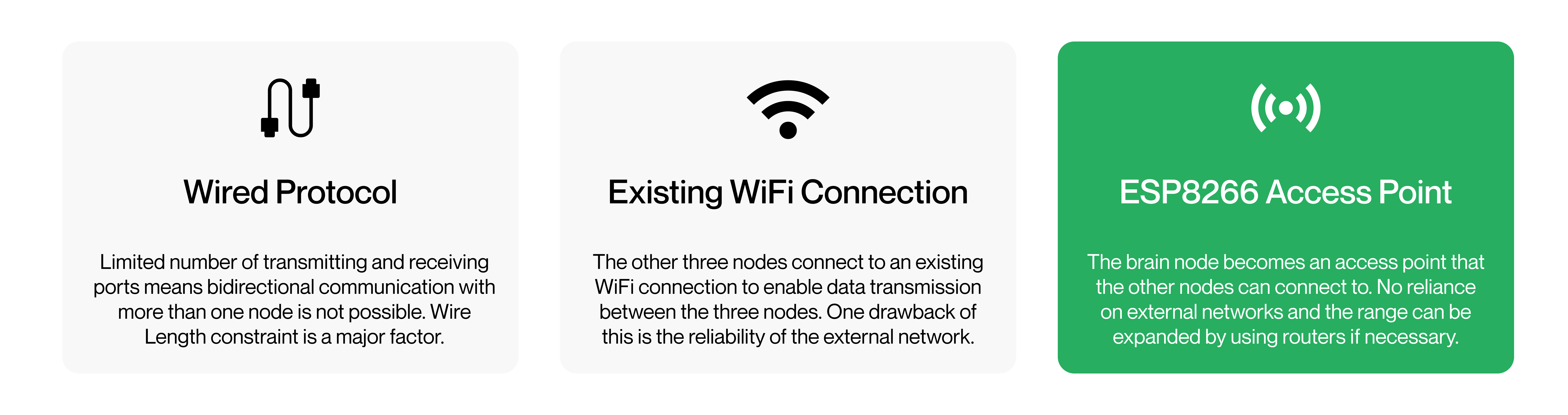
Initially, I explored using the ESP8266’s TX and RX pins for direct wired communication between nodes. However, this proved impractical: the Brain Node needs bidirectional links to both the Inside and Outside nodes, but the ESP8266 has too few serial ports to support this. Wiring also imposes strict distance limitations, forcing all nodes to be close together—defeating the purpose of a distributed system.
To overcome these issues, I turned to WiFi. There were two main approaches: either connect all nodes over an existing WiFi network, or have the Brain Node act as its own WiFi access point. While the first option depends on external network reliability, the second creates a private, self-contained network just for this system. This ensures stable communication, no matter the external infrastructure.
I chose the access point method for its autonomy and consistency. The Brain Node hosts the network, while the other nodes join as clients, maintaining robust and predictable communication.
For data exchange, I used JSON over HTTP, leveraging Arduino libraries for efficient encoding and parsing. To keep everything synchronized, I implemented a timeout on the client nodes—essentially a wait period before expecting the next response. This accounts for the variable time the Brain Node might take to process data, especially as more nodes are added in the future.
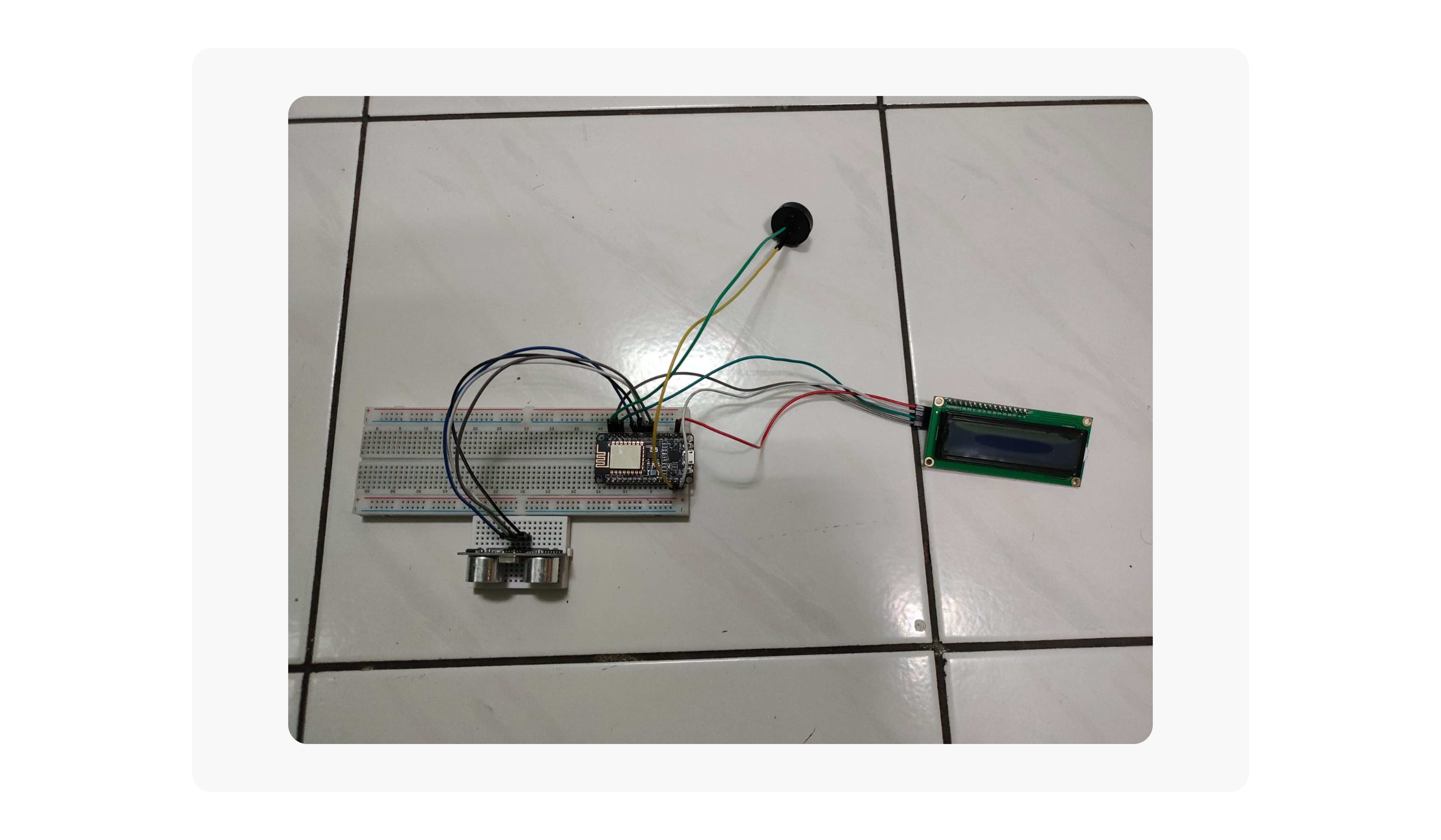
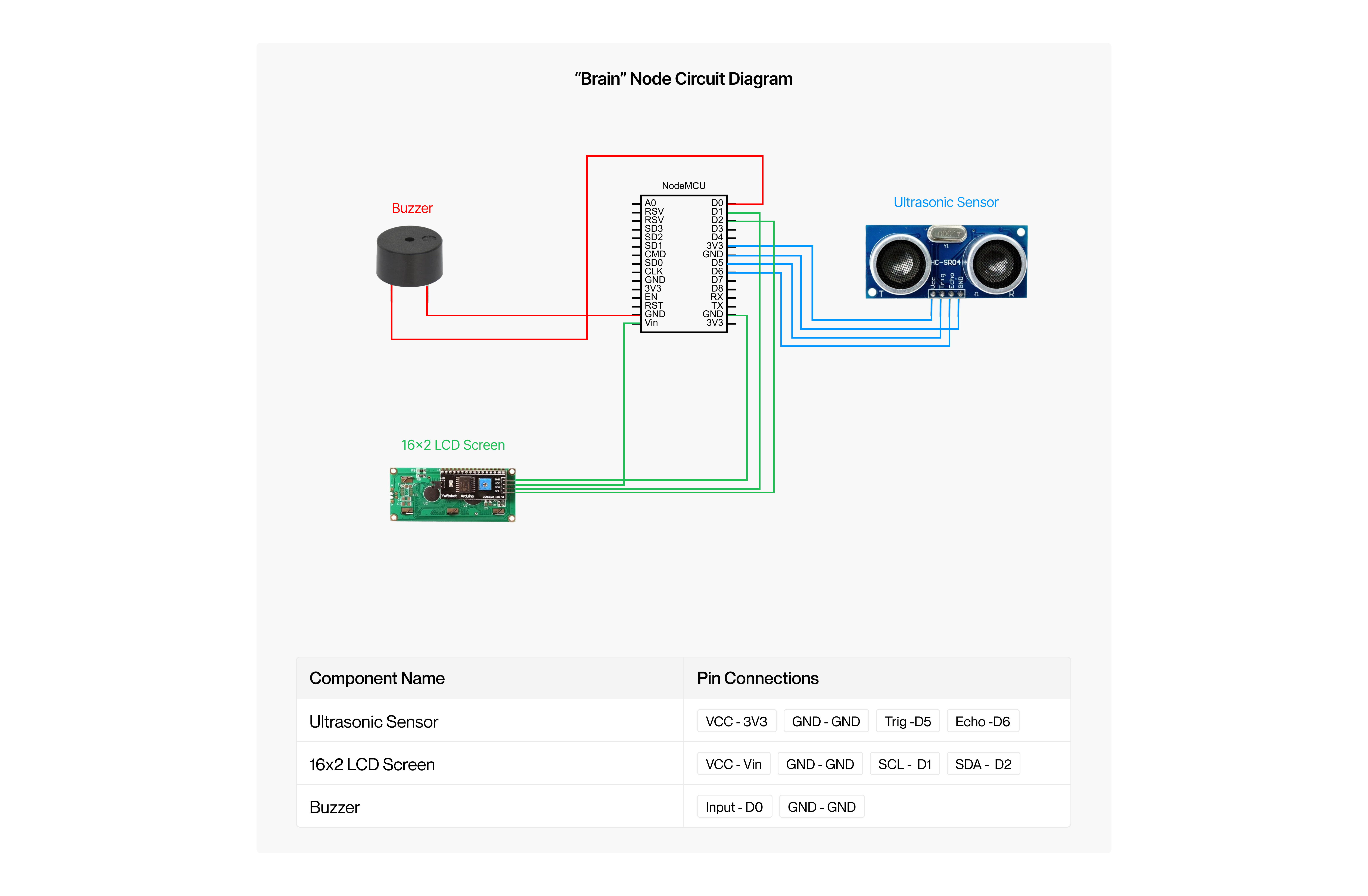
The Brain Node acts as the system's central controller and WiFi access point. It receives sensor data from the Inside and Outside nodes, compares it against stored optimal conditions, and sends back control signals to manage the actuators. It also hosts the web dashboard, letting users monitor readings, adjust targets, and manually operate devices.
This node integrates an ultrasonic sensor and buzzer to track the water reservoir level. If the water drops too low, the buzzer alerts the user, ensuring the system always has water available for irrigation. An LCD screen displays live data—such as temperature, humidity, soil moisture, and the IP address to access the dashboard—providing a quick local overview of the greenhouse conditions.
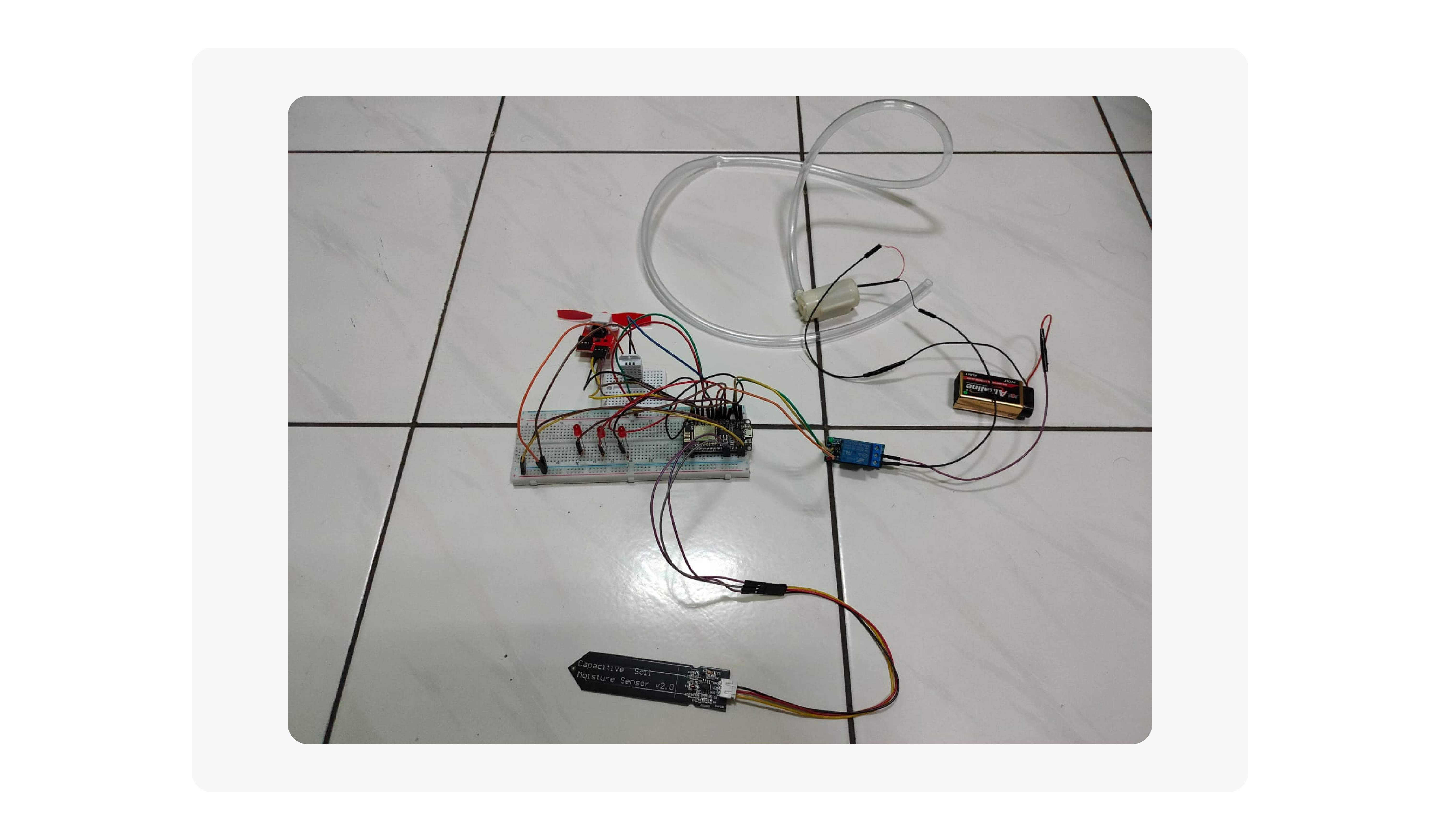
The Inside Node monitors and manages the internal environment of the greenhouse. It connects to the access point hosted by the Brain Node, sending sensor data in JSON format and receiving control flags in return.
This node houses the DHT22 temperature and humidity sensor, soil moisture sensor, L9110 fan module, submersible pump, and LED lights. It continuously reports internal readings to the Brain Node, which then decides when to activate the fan or irrigation pump based on optimal thresholds. While the LED lights are physically part of this node, they are triggered by light readings from the Outside Node's LDR module, ensuring lighting adjusts to external conditions.
The Outside Node operates much like the Inside Node but focuses on monitoring and managing external conditions around the greenhouse.
It includes an LDR module, rainfall sensor, micro servo, and an additional L9110 fan. When rainfall is detected, the node sends this data to the Brain Node, which replies with a control flag to open the servo — simulating a rainwater harvesting system. If ambient light levels drop too low, the LDR triggers a signal to the Brain Node, which then instructs the Inside Node to turn on the LED lights. Meanwhile, the outside fan operates under Brain Node commands based on interior readings. This setup demonstrates the system’s ability to coordinate actions across nodes, highlighting the flexibility and reliability of its communication protocol.
The web dashboard is embedded directly into the Brain Node using the Arduino IDE. As the system’s access point, the Brain Node hosts this interface, which users can view by connecting to its IP address.
The interface provides near real-time monitoring of greenhouse conditions, leveraging Ajax requests to update sensor data from both the Inside and Outside Nodes. A deliberate delay is added to balance performance, reducing load on the Brain Node while still delivering timely updates—appropriate since greenhouse conditions don’t change dramatically within seconds.
The second major feature of the dashboard is control. This interface allows users to manually operate all actuators in the system.
A key challenge was preventing conflicts between manual actions and automated decisions. For example, if a user turns off the water pump because the reservoir is low, the system might otherwise turn it back on automatically if it detects dry soil—defeating the purpose of manual intervention.
To address this, I implemented a 'Manual Override' feature. When activated, it stops all automated actions and lets users take full control of each actuator, regardless of current sensor readings. Once deactivated, the system resumes normal automated control. The dashboard clearly shows whether manual override is active, giving users confidence to adjust settings as needed for special cases or emergencies.
The last key feature of the dashboard is the ability to set optimal growing conditions. Research shows that different crops require different temperature, humidity, and soil moisture levels. Using static preset values could harm new plant cycles. By letting users adjust these parameters directly, the system can adapt to any crop, supporting healthier growth and making full use of greenhouse advantages over open field farming.
Overall, the dashboard is a critical addition to this IoT system. It combines real-time monitoring, manual control, and easy optimization of target conditions in a single, user-friendly interface—giving users precise control over their greenhouse environment.
In conclusion, this IoT system delivers a tailored solution for small-scale greenhouse management. Its modular architecture—centered on the Brain, Inside, and Outside nodes—supports flexible monitoring and control, with a robust communication protocol that makes it easy to add more nodes as needed. Automated rainwater collection, adaptive lighting, and the integrated web dashboard—offering real-time data and intuitive manual controls—together maximize resource use and sustainability. Designed for smaller operations, this system lays the groundwork for future scaling to larger agricultural applications.
https://www.granthaalayahpublication.org/journals/granthaalayah/article/view/IJRG19_A02_2128/883